
What?
Instead of passing food across the dinner table like a dirty mongoloid, these line following robots drive around your dining table trying their best to present your guests with food.I just googled the word mongoloid, and it does not mean what I thought it meant. I would like to apologize to any mongoloids I may have offended.
Why?
Last year for Thanksgiving I built a gravy train and this year I wanted to build a line following robot sushi conveyor belt.Video
Materials
Files
Fusion 360 file and Arduino CodeDesign
I've started using Fusion 360 instead of SolidWorks because it's cheaper. SolidWorks costs ~$3k for a basic license while Fusion is cheap or free for non-commercial use.My thoughts on Fusion 360:
- It will get the job done (sometimes painfully)
- Joints cause more problems than they solve
- I don't really like cloud saving
- Built in CAM is awesome
- It's affordable
In SolidWorks mates are used to relate parts to one another. Each mate added to a part further restricts degrees of freedom. They are extremely intuitive.
In Fusion joints describe the entire relationship between two points. Literally. You select two points then click the degrees of freedom you want to remain.
 |
| Fusion 360 joints |
Every joint tutorial I've seen only shows the assembly of completed components. Joints are PERFECT for assembling completed components, but that's not how I design things!! When I design in CAD my goal is to position parts relative to each other before creating the features that join them together!
IDK... this post isn't to crap on Fusion 360, but it's been driving me nuts for a while now.
Here's the model
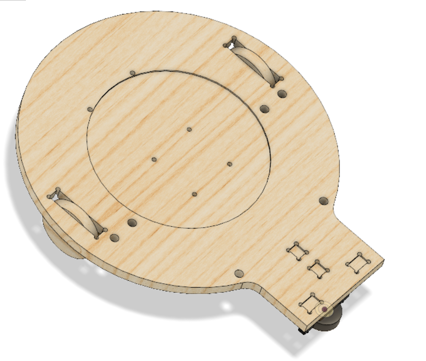 |
| top |
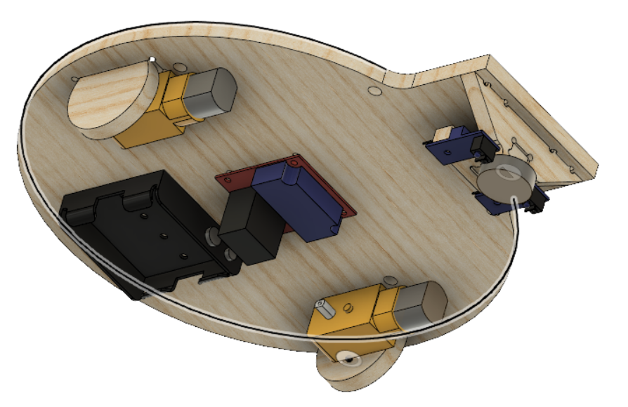 |
| bottom |
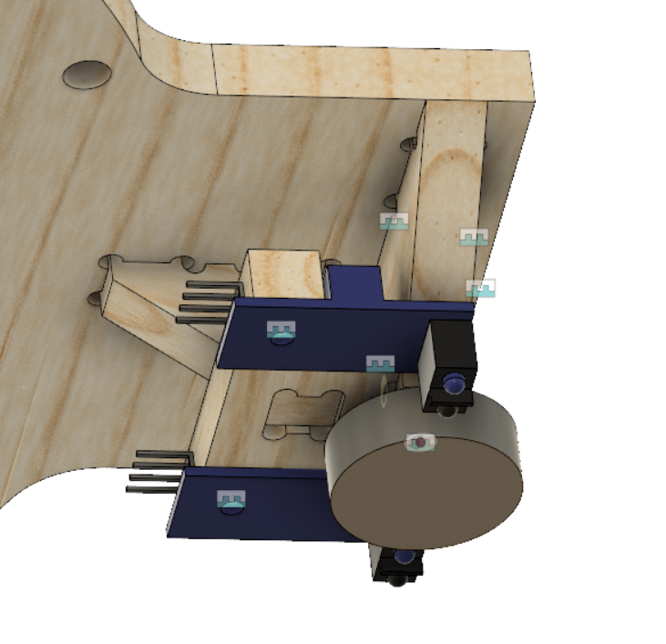 |
| Tab and slot |
I don't know dude, it just feels like joints are worse than mates. Conspiracy theory: Autodesk knows this and is keeping joints in Fusion as to not obsolete their higher end CAD packages (Inventor).
Electronics
The electronics for this project are really simple. This motor drive has a 5v regulator on it which you can use to power the arduino and IR sensors. Hook the IR sensors up to 5v/GND/D0.Adjust the screw pot on the IR sensors so that they can detect the difference between the line and non-line. This is the threshold that determines when the D0 pin changes state.
Firmware
Simple line following robots, hands down, are a fantastic beginning robotics project. They are so freaking simple.If the left sensor is over the line, you know the robot needs to steer left.
If the right sensor is over the line, you know the robot needs to steer right.
If neither sensor is over the line, you know the robot can keep driving forward.
Finally, if both sensors are over the line something has gone horribly wrong and maybe you could try driving backwards???
void loop() {
drive();
}
void drive(void){
bool sensor_right = digitalRead(SENSOR_R_D0);
bool sensor_left = digitalRead(SENSOR_L_D0);
if (!sensor_right && !sensor_left) goForward();
else if (sensor_right) goRight();
else goLeft();
}
It's that simple, full code is available to download above.
Problems
If you're having issues, make sure the sensors are detecting the line.Making the line thicker will help the robot respond in time.
Try moving the sensors farther apart?
Idk..
Conclusion
Line following robots are super cool and very easy to make. You can try making fancier firmware using the analog signals, or maybe even a single sensor??Byeeee
Information is very informative also you can click Nexter ,and get such type of info, this is the great resource to get such type of information.
ReplyDeleteHey William what software do you use to setup cut paths and send them to the x carve? We are trying to do curves like you did with the wooden bearings. Thanks for the help.
ReplyDeleteThat's the great idea one
ReplyDeleteAny chance you’ll be doing your blog again anytime?
ReplyDeletec h e e s e
ReplyDeleteHey William, by any chance would you like a phucking b e e s e c h u r g e r?
ReplyDeletewhat happened to doing stuff on this website William???
ReplyDelete